This controller is very similar to the original wired GameCube controller, so some information will not be repeated here. Some parts might be incomplete or missing, if you have anything that’s not listed in here, feel free to contact me!
Huge thanks to Shank and Madmorda for their knowledge and resources!
All the controllers and receivers are compatible together. If your WaveBird does not work, see the “Troubleshooting Common Issues” section.
Table of Contents
- PCB Variants
- Receiver
- RF Info
- Battery Compartment
- Shells and Other Parts
- Troubleshooting Common Issues
- Resources and Traces
1. PCB Variants
Four variants of the board are known; however they’re all very similar. I will only show one of the variants here, the differences will be shown later in this guide, as they’re all electronics variations. They all have T2 stickboxes. I might be missing some board variants, if you have anything different please let me know!


Main Boards:
- 23-0975A1
- 23-0975A2
- 23-1035B1
- 23-1035C0
C-stick:
- 23-1014A
- 23-1036A0
Triggers:
- 23-0901
- 23-1037A0
2. Receiver
All the receivers share the same internals and are compatible with all the WaveBird controllers. All of them are grey, except for the Gundam Char WaveBird receiver that is copper red. The part number on the receiver’s board is 19-B315.
A complete teardown of a receiver would take too many pictures, I invite you to check this one instead: Ifixit receiver teardown
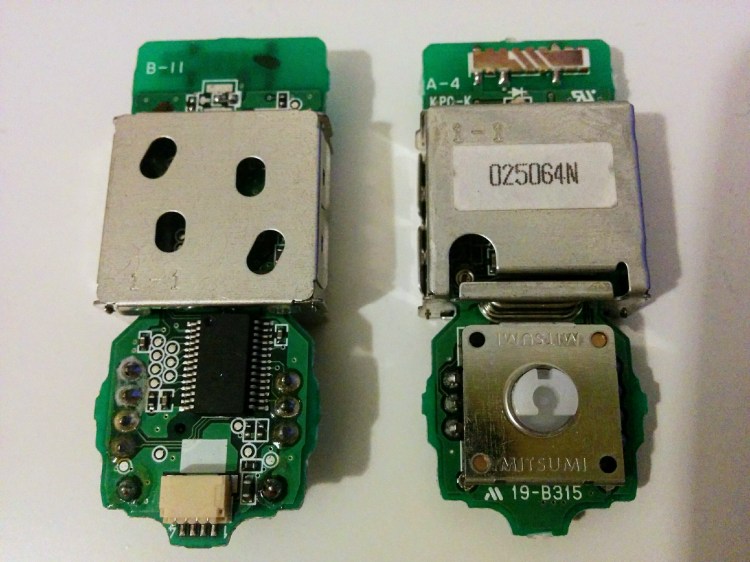
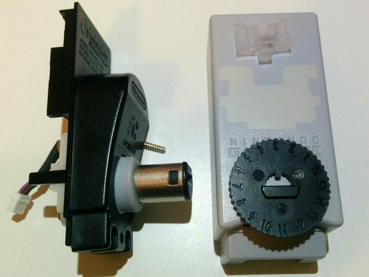
Here you have all the components of the receiver. On the left you have both sides of the board. On the top of the rightmost board you can see the rectangular copper antenna. The metal casing is a RF (radio-frequency) shield, and the big metal square is the 16 steps rotary switch for the channels. The black wheel on the right goes on top of it, one edge extrudes from the grey casing and you can turn the channels. On the right you can see the plug module, which can be disassembled further, but there’s not much to it. On the top right you can see a bit of clear plastic, which is used to amplify the light from the diode LED on the board, which is right under the antenna. And finally, the small sheet of white plastic is used to shield the electronics from interference from the cable.
Here’s how to place the small white plastic sheet when you reassemble the receiver. It shields the chip from interference caused by the wires.
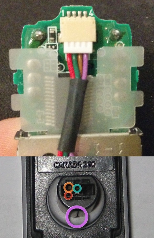
The receiver only uses four wires:
3.43V logic supply (pin 1)
Data (pin 2)
Ground (pin 3)
Shield (pin 4)
3. RF Info
Once again, all the WaveBird and receivers are compatible as they all use the same 2.4 GHz technology. The 900 MHz WaveBird does not exist. Through 16 different channels, the frequencies range from 2,404.8 MHz to 2479.2 MHz.
Note: This was tested by the FCC, and they note that their results are not 100% accurate. See their test report for more details.
| Channel | Frequency (MHz) | Channel | Frequency (MHz) |
|---|---|---|---|
| 1 | 2479.2 | 9 | 2438.4 |
| 2 | 2474.4 | 10 | 2433.6 |
| 3 | 2404.8 | 11 | 2445.6 |
| 4 | 2409.6 | 12 | 2450.4 |
| 5 | 2419.4 | 13 | 2460.0 |
| 6 | 2414.4 | 14 | 2455.2 |
| 7 | 2424.0 | 15 | 2464.8 |
| 8 | 2428.8 | 16 | 2469.6 |
Lowest Frequency Channel: 3 (2404.8 MHz)
Middle Frequency Channel: 9 (2438.4 MHz)
Highest Frequency Channel: 1 (2479.2 MHz)


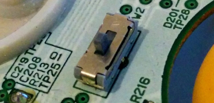
While both the controller and the receiver use the same 16 steps rotary switch, their logic is reversed on the circuitry: the 1st channel on the WaveBird will match the switch position of the 9th channel on the receiver. This isn’t noticeable when the units are closed, but it might be a nice tool for modding or troubleshooting.
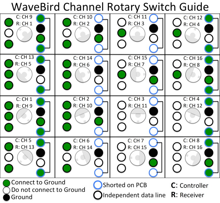
You might notice that on the 3rd channel for the controller (or 11th channel for the receiver), there are no green pins. The knob faces up, and the current completely bypasses the switch. If the rotary switch is defective on either unit, those positions are going to work anyway.
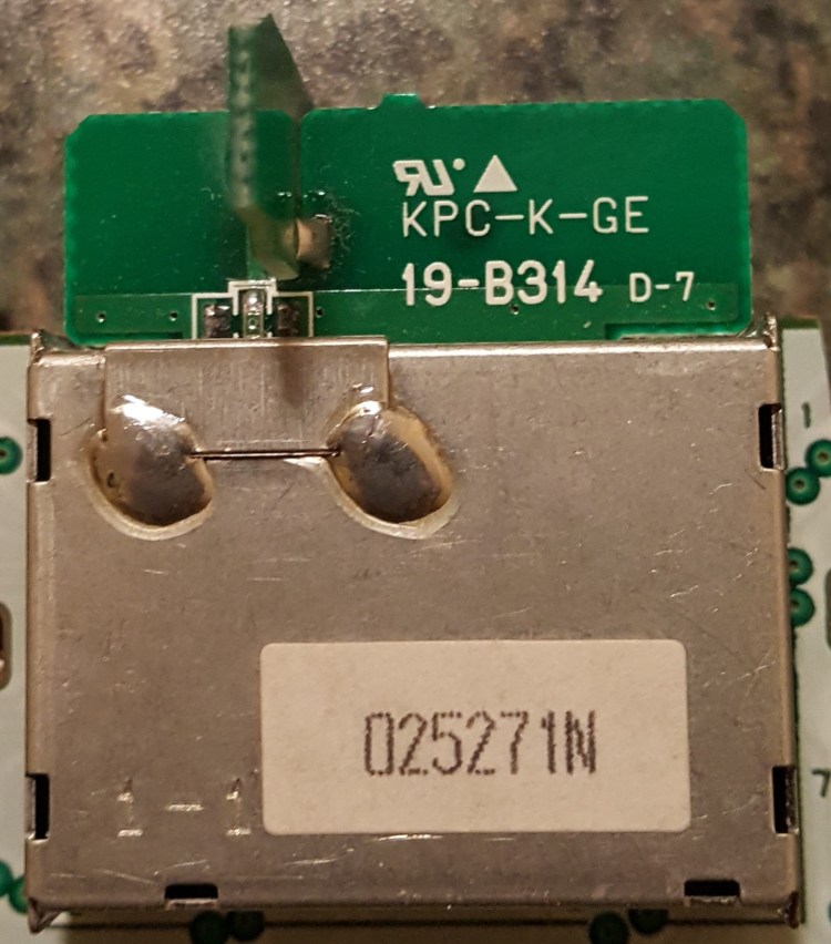
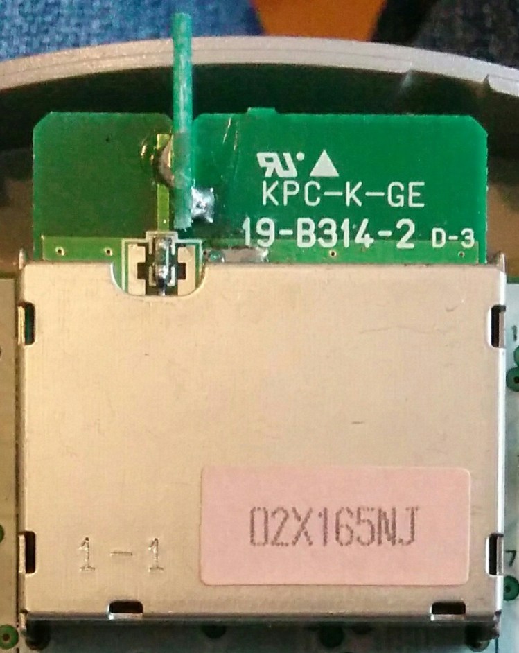
There were two versions of the WaveBird’s antenna. The first one used a MegaChips chip, then a revision came later on with the Mitsubishi chip. It increased the effective range of the WaveBird controller, and remained compatible with the previous hardware. They are denoted as “19-B314” and “19-B314-2”.

As far as I know, the receiver’s antenna remained the same throughout the entirety of the WaveBird’s production. Unlike the WaveBird’s antenna, this small rectangular copper antenna is not coated and has a vile tendency to corrode, which can cause it to stop working.
4. Battery Compartment
The battery compartment of the WaveBird holds two AA batteries in series, which pushes 3 volts through the circuit. The two bottom contacts are linked, while the two top contacts are connected to the main PCB (printed circuit board).


Here are the contacts and where they are connected to the main PCB. Those have a nasty habit of corroding, often from a leak from the batteries. they also hold the triggers bracket in place when soldered on.


5. Shells and Other Parts
Not to go too much in details, I’ll point out a few parts that are unique to the WaveBird that haven’t been shown anywhere else in this guide or in the original wired GCC internals guide.

The faceplate part of the front shell (where the inked “Nintendo GameCube” logo is) stands slightly higher than its wired counterpart to allow the antenna to fit. Because of this, the start button has to be slightly taller to compensate. The bottom is also extended to allow more circuitry, and to fit a on/off switch slot. The back shell also allows more space for the battery compartment, and the d-pad has a much better support inside the shell than the wired controller, which makes it a much better experience to use. The front shell also has extra markings aside from the “START/PAUSE”: “ON” and “OFF” around the power switch, “POWER” under the LED and “WAVEBIRD” at the bottom.

The Grey WaveBird sports a set of lighter-colored grey buttons, stick and switches. You can also notice the small piece of clear plastic used to amplify the light from the LED.

As said above, here’s the taller WaveBird start button on the left, used to compensate the height of the faceplate. Also, you can see the on/off switch here, which is located in between the D-pad and the C-stick. This is activated by the small rectangular piece of plastic you can see above. It is shown in the “off” position, the circuit is open.
6. Troubleshooting Common Issues
Once again, all the WaveBird and receivers are compatible. If your WaveBird does not connect to the receiver, there’s a high chance it’s one of four things: The receiver’s antenna, the battery contacts, or both rotary switches. Let’s break it down.
- Install a brand new pair of AA batteries. If the WaveBird’s orange LED light on the front does not light up, it’s most likely the battery connectors that are corroded. You need to unsolder them from the board and/or remove the lower one from the battery compartment (See the Battery Compartment section).
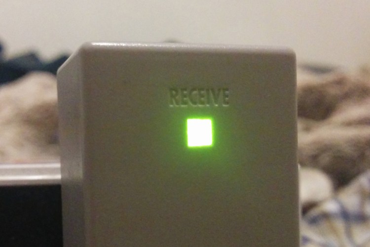
There’s a few ways to clean corrosion, but personally I use white vinegar. Soak the affected parts and brush it off. make sure to rinse them thoroughly afterwards, dry them off and solder them back on. If the orange LED lights up on the front when the switch is turned on, the current is going through.

- If the WaveBird turns on but can’t connect to the receiver, it might be the receiver’s antenna that is corroded. Open up the receiver and locate the antenna (See the Receiver or RF Info sections). If it’s covered in a brown crust, take very fine sandpaper (2000 grit and above) and gently rub the surface until it’s clean. Then, using rubbing alcohol, clean it. Let it dry, reassemble and test it with both units on the same channel.
If the green LED on the front lights up, that means the receiver is connected to the controller and it should be working. Note that the antenna can go bad again, you might have to clean it again in the future. Also, it’s advised to clean up the interior of the plug itself with a cotton swab and rubbing alcohol to make sure there is no dirt or corrosion on the pins.

- If the receiver still does not light up after those two steps above, it might be an issue with the rotary switches for the channels. It’s great to have extra functioning WaveBird hardware for this step, as if both units are defective, there’s no way to tell.
The switch has a neutral position where the logic of the board completely bypasses it (See the RF Info chart). That means the affected hardware will still be able to communicate through a specific channel. If the 3rd channel works, the controller’s rotary switch is defective. If the 11th channel works, the receiver’s rotary switch is defective.
If you don’t have a spare 16 step rotary switch to replace the defective one, you can either keep it on the working channel, or since it’s an issue with contacts corrosion, you can try to spin the switch really fast for about 20 turns. Often, that dislodges enough corrosion to make it work properly again. - I’ve been told that cleaning the ports on both the GameCube and the receiver can help solve an unstable connection. The receiver might be more sensible to slight electrical variations due to corrosion. Clean the ports with a cotton swab and rubbing alcohol and let it dry. Thanks to Leo for the feedback!
If all of the above still does not fix your connectivity issues, make sure the controller PCB is not cracked or damaged. If the WaveBird or the receiver has been tampered with prior to the issues, I’m not sure I would be able to help.
7. Resources and Traces
Resources
- Parts list from the FCC for the WaveBird: Website
- Shank’s WaveBird Rotary Switch Guide: BitBuild Forum Thread
- Full receiver teardown: IFIXIT Guide
- Noble potentiometers catalogue: PDF Document
- Nintendo Gamecube Controller Protocol: Website
- The Mystery of the 900 MHz WaveBird
Traces
- ★ Madmorda’s Wavebird Board Scans and Documentation: BitBuilt Forum Thread
